


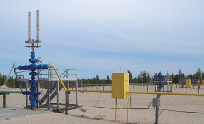
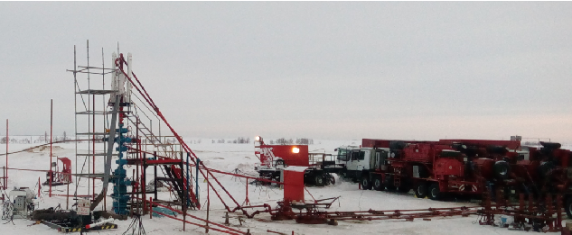
Tree saver is intended for the protection of wellhead equipment against high pressure when technological works on gas and oil well related to injection into the formation (hydraulic fracturing, treatment of bottom- hole area, etc.).
Tree saver consists of a top (movable) plate, a bottom (fixed) plate, two hydraulic cylinders, a protective cover. On the top plate an adapter with a nut and a hollow stem, hydraulic cylinders are mounted. On the bottom plate, a housing with a nut is mounted. Hydraulic cylinder rods are connected with the bottom plate.
Depending on diameter of oil string and height of the tree a hollow stem, nozzles, extension inserts are selected and assembled with the adapter forming a central hole of the well.
Tree saver with closed plates (the central hole is pulled into the body), the removed casing and the installed nozzle (extension insert) is fastened to the tree via the flange adapter. The gate valve of the tree is open, a hollow stem is entered with the set speed into the tubing (plates of the saver are closed). The nozzle (the top cup of the nozzle) should be entered into the tubing to 300… 350 mm. The tree equipment is protected from influence of technological fluids (processing medium). Injection into formation (into the well) is made from the line of the manifold unit through the central hole. On inlets of the central hole (the central line) and annular space of the saver shutdown valves are mounted. After closing of plates the adapter of the top plate is connected to the body of the bottom plate by means of the nut, creating thereby one whole rigid construction (with the tree equipment).
After inlet of a nozzle into the tubing of the well (packing) a space between internal diameter of the body, outer diameter of the hollow stem and internal space of the tree is formed. This space is shut down by nozzle cups from the internal diameter of the tubing of the well and is designated as “annular space” of the tree saver. The annular space serves for an increase in reliability of action of cups through the pressurizing (back pressure) in this annular space and also for emergency depressurizing. In order to do that a supplying nipple is installed in the body of the bottom plate. The annular space is interconnected with the well after outlet of the nozzle from the tubing (packer release) and before the closing of the gate valve of the tree and this annular space must comply with the expected pressure in the well after carrying out technological operation
For the drive of the tree saver an autonomous hydraulic station or a hydraulic drive of the crane- manipulator are used.
On January 25, 2016, in the LLC “Weatherford” a tree saver with the hydraulic drive – Hydraulic Tree Saver (AFP-06-04) was put into operation.
Maximum working pressure:
- in the central line (well hole) – 105 MPa (1050 kp/cm2)
- in the line of annular space – 70 MPa (700 kp/cm2)
In 2016 our enterprise has delivered six tree savers. Main customers of this equipment were CJSC “SP MeKaMineft”, LLC “Weatherford”, LLC “Eriell Neftegazservice”, LLC “FracJet-Volga”.
The complete description of Tree Saver can be downloaded here